
Have you ever thought of developing your own smart security camera or a cool robot with vision capacity ever? 🤖📷 Then, the ESP32-CAM can be the right tool to make that dream a reality! What you’re holding in your hand is a tiny powerhouse of functionality that leverages ESP32 microcontroller plus integrated camera capabilities, opportunities for IoT and computer vision are immense.
But we know what you’re thinking: But isn’t starting with ESP32-CAM complicated?” Don’t worry! We’ve got you covered. This is a step by step guide from being an ESP32-CAM beginner to being an expert in this SoC. In this tutorial, we’ll take you by the hand from the ground up, from getting the concept to installing the development tools, programming your device, and even creating your first application.
Are you ready to undertook this fantastic journey? Well, let’s go directly to the chapter and get to know ESP32-CAM in detail, from the basics to the intermediate and advanced methods, together with the recommended practices. By the end of this roadmap, you’ll be equipped with all those things which can help in creating your creative ideas into a reality!
Understanding ESP32-CAM Basics
What is ESP32-CAM?
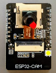
The ESP32-CAM is a high performance and multifunctional development board that includes the ESP32 wireless microcontroller and an onboard camera. This has turned out to be such a great option that we recommend for projects in the IoT sector that need vision. This nicely sized gadget comes with a punch with Wireless and Bluetooth integration, making it perfect for wireless surveillance.
Key features and capabilities
The ESP32-CAM boasts an impressive array of features that set it apart from other microcontrollers:
- High-resolution camera: Up to 2MP with adjustable resolution
- Powerful processor: Dual-core 32-bit CPU
- Wireless connectivity: Built-in Wi-Fi and Bluetooth
- Expandable storage: MicroSD card slot for image storage
- Programmable GPIO pins: For connecting sensors and actuators
Comparing ESP32-CAM to other microcontrollers
Let’s compare the ESP32-CAM to some popular alternatives:
| Feature | ESP32-CAM | Arduino Uno | Raspberry Pi Zero W |
|---|---|---|---|
| Camera | Built-in | External module required | External module required |
| Wi-Fi | Yes | No (requires module) | Yes |
| Bluetooth | Yes | No (requires module) | Yes |
| Processing power | Dual-core 32-bit | Single-core 8-bit | Single-core 32-bit |
| Price | Low | Low | Medium |
Common use cases and applications
We’ve seen the ESP32-CAM used in a variety of exciting projects:
- Home security systems
- Wildlife monitoring
- Smart doorbells
- Robot vision
- Object detection and tracking
For such applications and many more it is therefore well suited because of the camera capabilities accorded to it, wireless connectivity and low power consumption. In the next sections, we will see how to make the most of ESP32-CAM in our projects.
Setting Up Your Development Environment
A. Required hardware components
To get started with ESP32-CAM development, we’ll need a few essential components. Here’s a list of the hardware you’ll need:
- ESP32-CAM module
- FTDI programmer or USB-to-TTL converter
- Breadboard
- Jumper wires
- Micro USB cable
- Power supply (3.3V)
- MicroSD card (optional, for storage)
| Component | Purpose |
|---|---|
| ESP32-CAM module | Main board with camera |
| FTDI programmer | For uploading code |
| Breadboard | For prototyping |
| Jumper wires | For connections |
| Micro USB cable | Power and data transfer |
| Power supply | To power the ESP32-CAM |
| MicroSD card | Optional storage |
B. Installing necessary software and drivers
Next, we’ll set up the software environment. Here’s what we need to install:
- Arduino IDE: Download and install the latest version from the official Arduino website.
- ESP32 board package: Add it to Arduino IDE using the Boards Manager.
- ESP32-CAM library: Install it through the Arduino Library Manager.
- CH340 driver: For FTDI programmer communication (if not automatically installed).
C. Configuring Arduino IDE for ESP32-CAM
Now that we have the software installed, let’s configure Arduino IDE:
- Open Arduino IDE
- Go to File > Preferences
- Add the ESP32 board manager URL in the “Additional Boards Manager URLs” field
- Install the ESP32 board package from Tools > Board > Boards Manager
- Select “AI Thinker ESP32-CAM” from Tools > Board
D. Troubleshooting common setup issues
If you encounter issues, try these solutions:
- Check all connections carefully
- Ensure correct COM port selection in Arduino IDE
- Verify power supply voltage (3.3V required)
- Double-check driver installation for FTDI programmer
- Reset ESP32-CAM before uploading code
With our development environment set up, we’re ready to start programming the ESP32-CAM.
Programming Your ESP32-CAM
Understanding the ESP32-CAM pin layout
Before we dive into programming, it’s crucial to familiarize ourselves with the ESP32-CAM’s pin layout. This knowledge will be essential for connecting peripherals and understanding how to interact with the board.
| Pin Group | Description | Key Pins |
|---|---|---|
| Power | Supply voltage and ground | 5V, 3.3V, GND |
| GPIO | General-purpose input/output | GPIO 0-16 |
| Camera | Dedicated camera interface | XCLK, PCLK, VSYNC, HREF |
| UART | Serial communication | U0RXD, U0TXD |
Writing your first “Hello World” program
Now that we’re familiar with the pin layout, let’s write our first program. We’ll use the Arduino IDE for this example:
- Open Arduino IDE
- Select “ESP32 Wrover Module” as the board
- Copy and paste the following code:
void setup() {
  Serial.begin(115200);
}

void loop() {
  Serial.println("Hello from ESP32-CAM!");
  delay(1000);
}- Upload the code to your ESP32-CAM
- Open the Serial Monitor to see the output
Exploring basic camera functions
With our “Hello World” program running, we can now explore some basic camera functions:
- Initializing the camera
- Capturing a single frame
- Adjusting camera settings (resolution, quality, etc.)
Capturing and Processing Images
Adjusting camera settings for optimal image quality
When working with the ESP32-CAM, we can fine-tune various camera settings to achieve the best possible image quality. Let’s explore some key parameters we can adjust:
- Resolution
- Brightness
- Contrast
- Saturation
- Special effects
Here’s a table summarizing the available resolution options:
| Resolution | Width | Height |
|---|---|---|
| UXGA | 1600 | 1200 |
| SXGA | 1280 | 1024 |
| XGA | 1024 | 768 |
| SVGA | 800 | 600 |
| VGA | 640 | 480 |
| CIF | 400 | 296 |
| QVGA | 320 | 240 |
| HQVGA | 240 | 176 |
| QQVGA | 160 | 120 |
We can adjust these settings using the sensor_t struct and sensor.set_xxx() functions in our code.
Storing captured images in memory
Once we’ve optimized our camera settings, we need to store the captured images. The ESP32-CAM has limited memory, so we must use it efficiently. We have two main options:
- Internal RAM: Fast but limited capacity
- microSD card: Slower but larger storage
For temporary storage or real-time processing, we typically use the internal RAM. However, for long-term storage or larger images, a microSD card is preferable.
Implementing basic image processing techniques
With our images captured and stored, we can now apply some basic processing techniques. Here are a few we can implement:
- Grayscale conversion
- Binary thresholding
- Edge detection
- Noise reduction
These techniques can help us prepare images for further analysis or improve their quality for specific applications.
Sending images over Wi-Fi
Finally, we can transmit our processed images over Wi-Fi. This is particularly useful for remote monitoring or IoT applications. We typically use HTTP POST requests or WebSocket connections to send images to a server or another device.
When implementing this feature, we need to consider factors like image compression, network stability, and data security. By optimizing these aspects, we can ensure efficient and reliable image transmission from our ESP32-CAM.
Very good https://is.gd/N1ikS2
Very good https://is.gd/N1ikS2
Good https://is.gd/N1ikS2